The third part of the hexapod tutorial series is here! With this we are one step closer to our hexapod robot moving around and showing us what it’s got! In the last tutorial we planned the electronics and now is time to discuss sizing, design electronics diagrams, do the PCB design, and to finally build and assemble them all together. To better understand this article, please read the previous two parts of the tutorial before embarking on this article.
In our last tutorial (Planning the Electronics) we have established all the electronic components needed for our robot. This means that now we can go further and lay out the electronics board. This board will also contain all the necessary electrical connections between the elements.
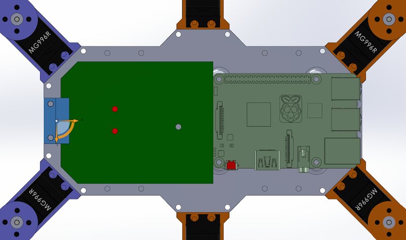
Before getting into it, we need to check the available space for this board. As we can see in the next image, we have already added the Raspberry Pi board to the 3D model. The remaining space from the left side is the available spot for the rest of the electronics.
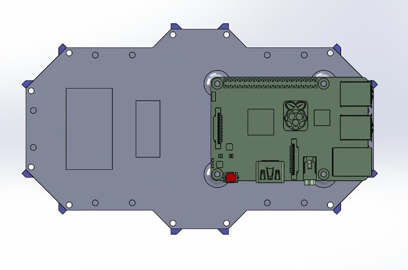
Robot body and the Raspberry Pi mounted in place
We need to know the exact dimensions of this available space, and in order to obtain this information, we design a part that simulates the electronics board and add it to the assembly. These dimensions are after fine tuning the dimensions in order to get the most out of that space.
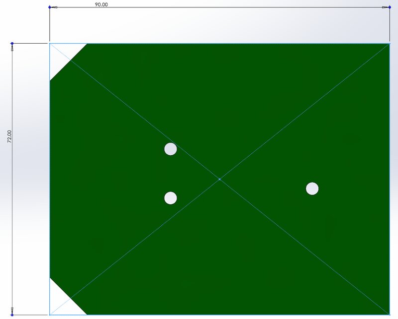
Simulated electronics with visible dimensions [dimensions are in mm]
Further, we added the electronics board to the assembly and checked how it integrates with the rest of the components.
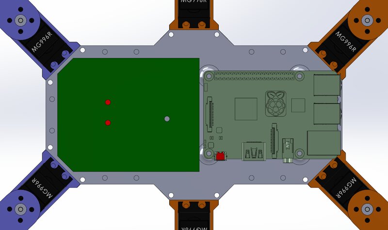
Robot body with the electronics board
Before going to the electronics design it is important to establish the mounting points for our new board. As we can see in the image above, we have already marked three mounting points for screws. However, two of them are going through the cable paths, so in order to avoid any problems, we have designed a new 3D part that will hold the electronics in place.
Robot body and the electronics board kept in place by the new 3D part
Now that we have the maximum size of the board, we can switch to an electronics design software such as Eagle and start adding components and connections. If you want to design this by yourself we recommend to also include the Eagle PCB library from sparkfun in order to add more layouts for more parts. In this case:
Always connect ground to ground, minus to minus and plus to plus. We will work only with positive voltages, so we will have ground as reference (noted by GND) and plus (noted with VCC or the voltage level used). As for the GPIO’s pins, they will be noted with different names according to their function or connections.
The first components that we will add to the design are the connections needed for all the servo motors. We have 18 servos, and that means we need 18 x 3 pin connections. In this setup, due to the lack of space we will use double connectors, so we will have only 9 elements in the circuit diagram (actually 10, because we added 2 connectors for spare).
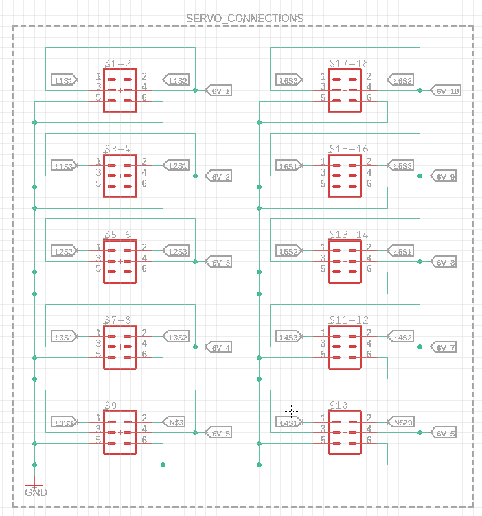 Circuit diagram for the 18 servo motors
As you can see in the diagram above, for each connector (S1-2, S15-16 and so on) there are electrical connections for the signal such as L1S1 (which is for leg 1 servo motor 1), the GND is common to all of the elements, and the power is splitted in several 6V power lines, which are shared to only 2 servo motors (6V_1 for example is the 6V power line for the first connector).
As we know from the previous tutorial, the chosen voltage regulators can only supply power to 2 servo motors, and this means we need 9 switching power supply in order to provide the required power.
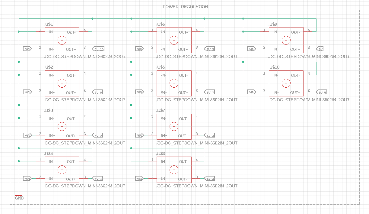
The switching power supplies needed for the robot
As we can see in the image above, there are actually 10 switching power supplies, and that is because one of those is needed for the Raspberry Pi itself.
Another important aspect is that, as you will see, if you try to design this by yourself there will be no component for the switching power supply, and that is because there is none. However, we have designed one, and added it to the original model, together with all the changes. You can find it on this link.
Going further we can take care of the end leg switches, but this also means that we need to add a GPIO expander. We are doing this because we want to plan for the future of the robot, and have more available GPIO if needed. If we don’t do this we will only have one or two more GPIO’s for other ideas or improvements that might come up in the future.
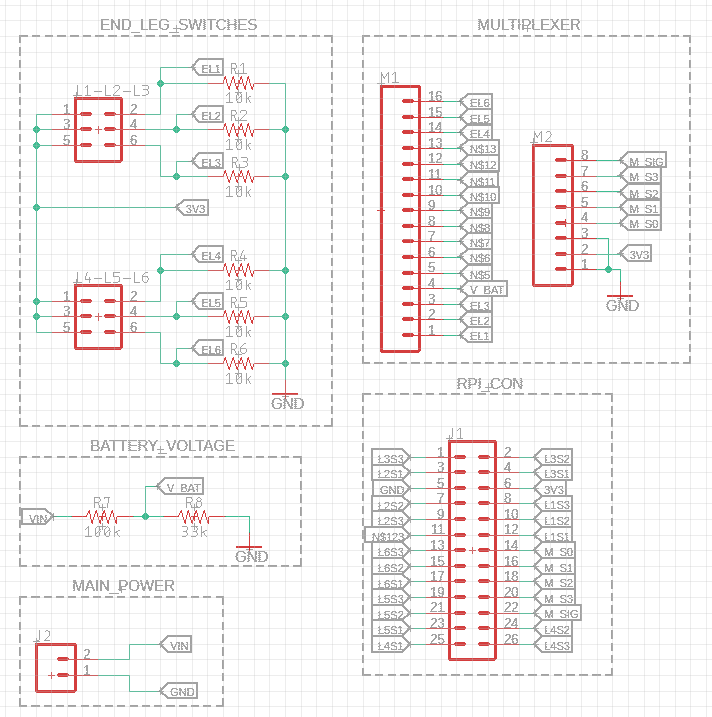 The remaining elements were added to the circuit diagram
As we can see in the above diagram, we have a GPIO expander that will take care of all the end leg switches but also the battery voltage circuit, and still have room for 9 more I/O’s.
It’s time to switch to the printed circuit board (PCB) design and lay out the position of all the elements. We will start with the perimeter of the board as we planned in the 3D model, and the result can be checked in the next image.
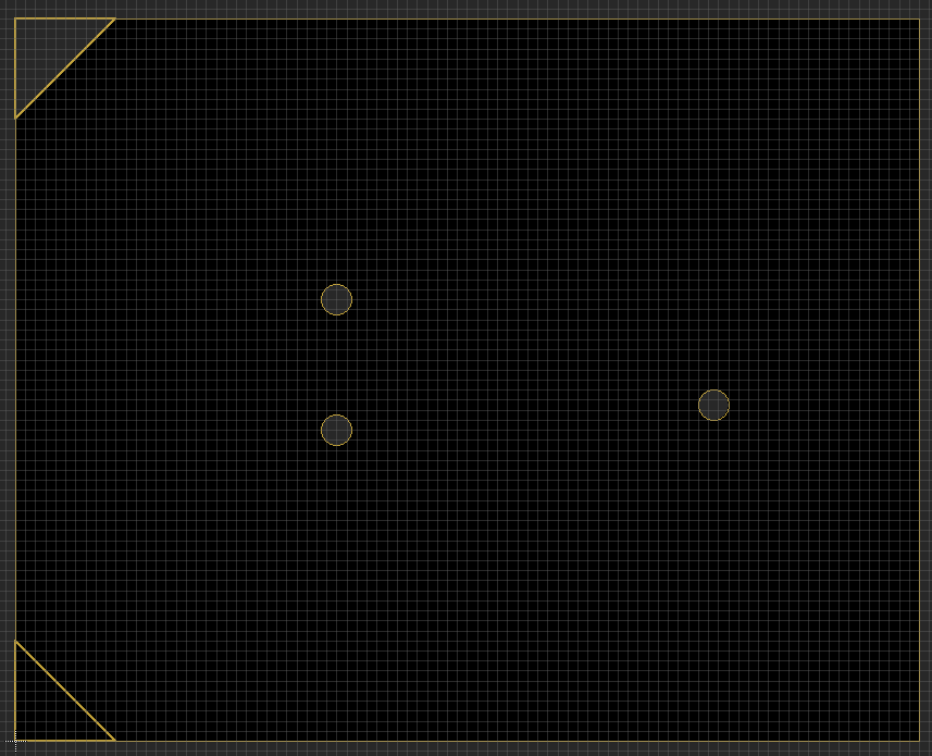
PCB maximum dimensions
The design of such a board is an iterative process, so we will make some progress and then lose some, but this is completely normal. We recommend starting by layouting the position of the elements first and after that start wiring the signals. Due to the small size, we were forced to do a double layered PCB, and this means that we have electrical connections on both sizes of the PCB. The final result can be checked in the next image.
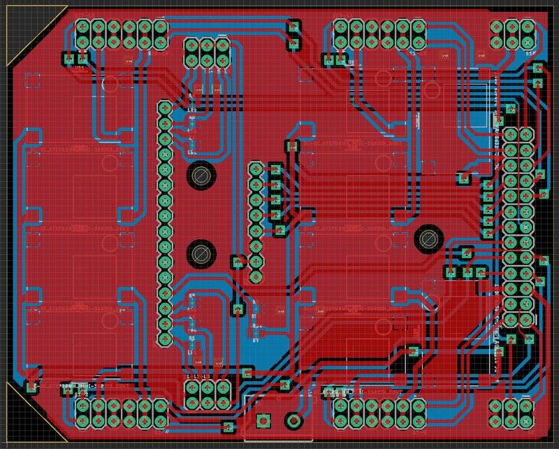
Final PCB design
The blue traces are situated on the bottom of the PCB and the red ones on top. We can even check them side by side to see the traces better.
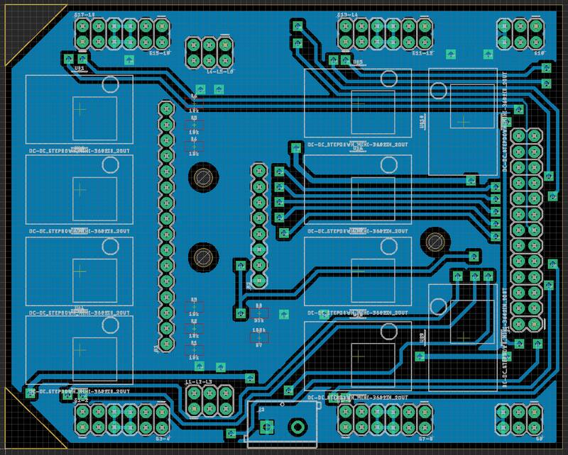
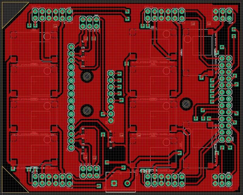
Circuit traces - the bottom traces (blue) and the top traces (red)
After this is done, we can export the part list used for this circuit, like in the following table:
|
Part |
Number of parts |
Value |
Device |
Package |
Library |
|
J1 |
1 |
CONN_13X22X13 |
2X13 |
SparkFun-Connectors |
|
|
J2 |
1 |
CONN_025MM |
SCREWTERMINAL-5MM-2 |
SparkFun-Connectors |
|
|
L1-L2-L3, L4-L5-L6 |
2 |
CONN_03X22X3_SILK_MALE_PTH |
2X3 |
SparkFun-Connectors |
|
|
M1 |
1 |
CONN_16 |
1X16 |
SparkFun-Connectors |
|
|
M2 |
1 |
CONN_08" |
1X08 |
SparkFun-Connectors |
|
|
R1 - R6 |
6 |
10k |
0.75OHM-0805-1/4W-1% |
805 |
SparkFun-Resistors |
|
R7 |
1 |
100k |
0.75OHM-0805-1/4W-1% |
805 |
SparkFun-Resistors |
|
R8 |
1 |
33k |
0.75OHM-0805-1/4W-1% |
805 |
SparkFun-Resistors |
|
S1-2, S3-4, S5-6, S7-8, S9, S10, S11-12, S13-14, S15-16, S17-18 |
10 |
CONN_03X22X3_SILK_MALE_PTH |
2X3 |
SparkFun-Connectors |
|
|
U$1 - U$10 |
10 |
DC-DC_STEPDOWN_MINI-3602IN_2OUT |
DC-DC_STEPDOWN_MINI-3602IN_2OUT |
2IN_2OUT |
My_Custom_Library |
After the design, we still need to build this circuit. We have several options to finish this step:
or
To find out what can be done in-house, we went for the second option and built it by ourselves, because this robot is in fact a prototype ?. The result can be seen in the following image:
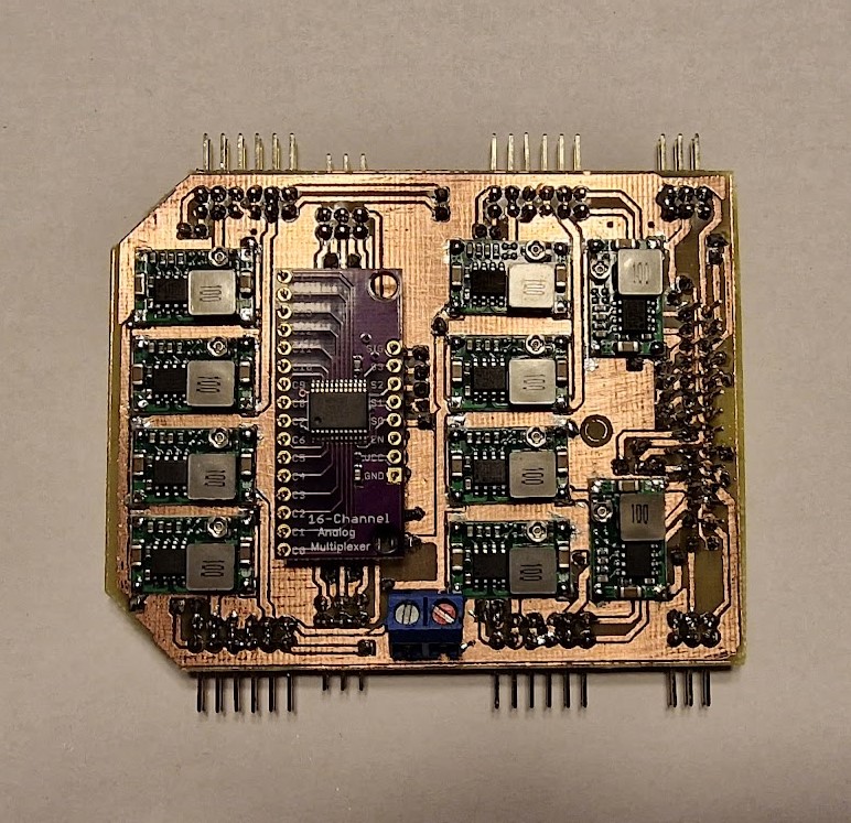
The circuit board that was built in-house
Now that we have built our electronics board, before connecting it to the motors and the Raspberry Pi we need to ensure that everything is working properly. And in order to achieve this we need to:
After all of this we can proceed to mount the board on the robot.
We have reached the step where we need to start the assembly process of the electronics on the robot itself.
We will start this process by adding the end-leg switches to the robot. To accomplish this, we need two M2x16 screws and two M2 nuts for each leg. We will also need a 6.6 x 33 x 0.7 compression spring that will retract the screw from the switch when the leg is not in contact with the ground anymore.
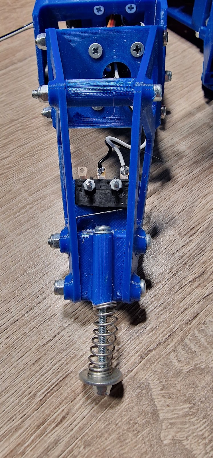
End leg switch together with the spring mounted
After we add this switch, along with the cable needed for it, we need to do some cable management. This is very important because the leg will move in time, and we don’t want to get it stuck and limit the leg movement. For this task we used some hot glue and temporarily soldered the cables on the case, but not before taking into account the full movement of the leg in all the directions. The result can be seen in the next image.
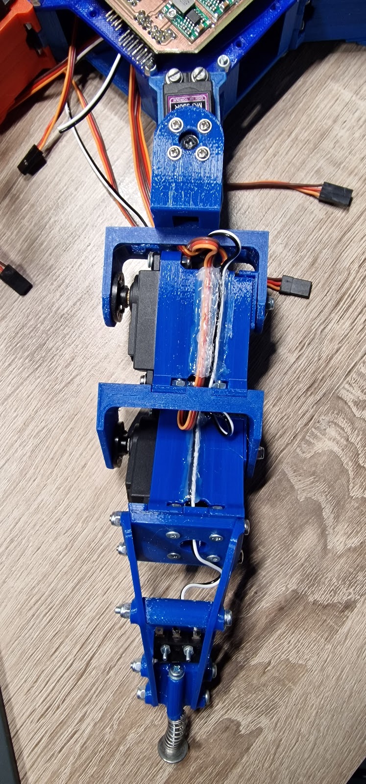 End leg switch and servo cables hold in place with hot glue
In the next step we need to mount the electronics board on the robot itself. This is an easy task, and can be done with only 3 screws as we can see in the next image:
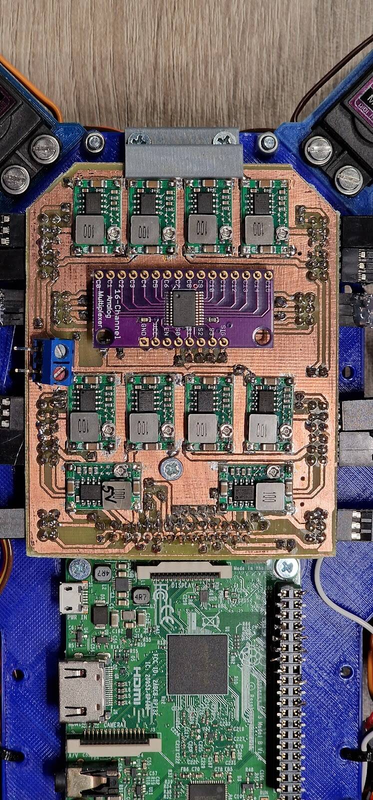 Electronics board assembled on the robot
The only thing that remains to be done is to connect everything up as we have planned during the designing of the electronics. Basically, we need to connect the motors in the following diagram:
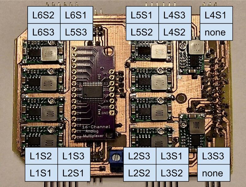
Servo motors connections positions on the board
If, for some reason, we can’t follow the initial plan, or we mess things up by connecting a servo on the wrong position, that is not a very big deal because in the programming part we need to map those servo connections to Raspberry Pi’s GPIO. That way, we can fix the errors that might appear during this step, so don’t worry too much.
Next, we need to use some cable ties in order to do some cable management and allow the robot to move freely. Also, please be aware that the back motors may need some servo cable extensions. The final result can be checked in the following image:
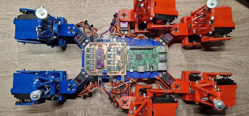
Servomotors and end switches connected to the electronics board
And there you have it! All the electronics are in place now, and we can proceed to the next part of the tutorial, where we program the robot itself. Stay tuned for the software part of how to build your own hexapod robot!
Alin Jderu has 14+ years of experience in custom robotics for competitions, taking on various roles, such as builder, mentor, referee and judge. He also has 9+ years of experience in IOT and 6+ years of experience in nanotechnology research and development and with organizing scientific education events. He has a programming background in C/C++, Python, HTML, Matlab, LabVIEW, electronics circuit design in Eagle and Proteus, 2D/3D CAD/CAM Design in Catia, Solidworks, Autocad, OpenSCAD and 3D printing, simulation software in Simulink, AmeSim, COMSOL Multiphysics and editing software in Photoshop and Corel Draw. You can also google him ;) He is currently working in IOT R&D at eSolutions.
Ready to learn more about how custom software products can benefit your business? Contact us today to schedule a consultation and start exploring your options!