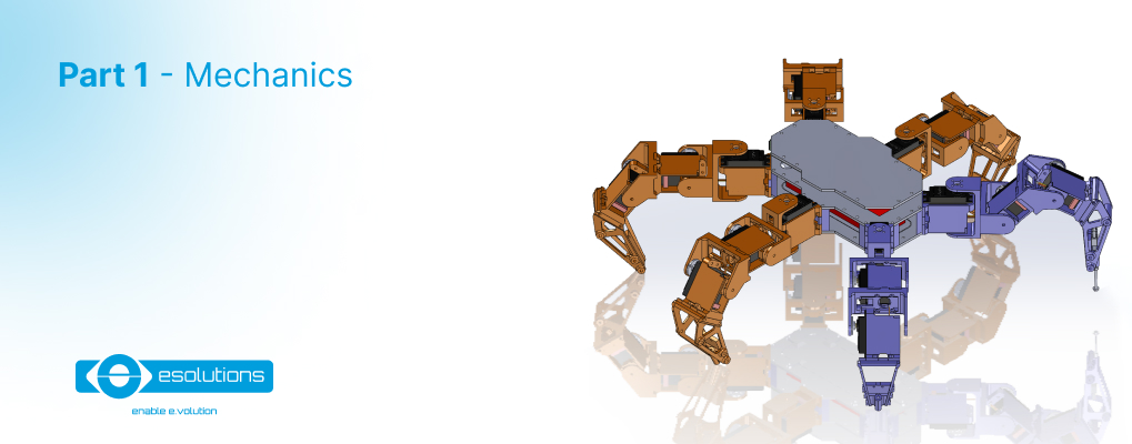
In this five-part tutorial we will present how to build a hexapod robot from scratch. We will go through all the details about the mechanics, electronics, and, of course, the software of our hexapod. If you want to see the real version of the hexapod in the cover photo, finish reading this article. Brace yourselves, cause this is going to be a long but interesting read!
Before starting this tutorial, we need to do a little research in order to see what option of hexapods we have out there. So we found some sources of inspiration, as follows:
After seeing all the designs that are out there, and considering all the pros and cons, we have a final solution for our tutorial:
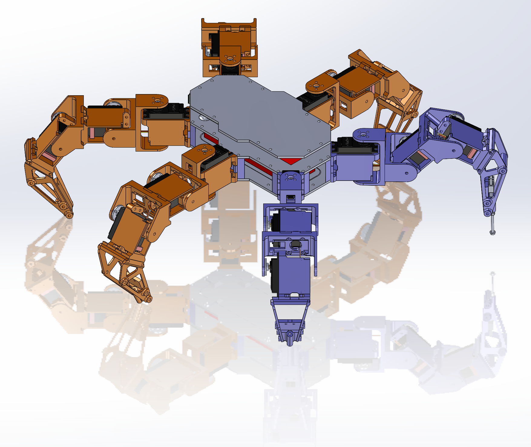
As we said before, we started from the hexapod design no. 1 and re-designed all pieces in order to implement our idea about this robot. Our final result is presented in the image below.
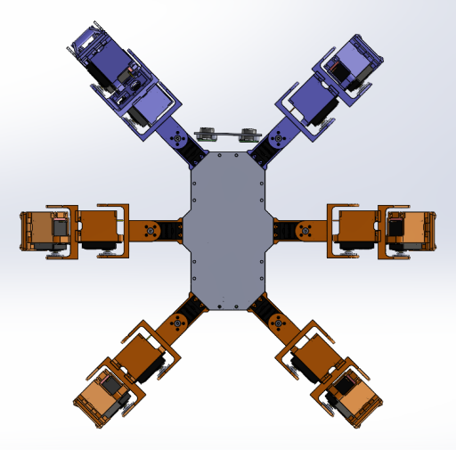
We can see in this picture that the robot is designed in a mirrored configuration. Also, we decided to 3D-print the front legs in another color in order to rapidly spot the face of the robot. The new design can be found and downloaded from here.
In order to build the robot you need to 3D print the following parts with the following configuration.
|
Parts necessary for one LEFT Leg |
|||||
|
Number of parts |
Part name |
Material |
Support? |
~ Material [g] |
~ Time [h] |
|
3 |
Servo_Mount_07 |
PETG |
YES |
57 |
9 |
|
3 |
Servo_Bearing_Fixer_02 |
PETG |
NO |
3 |
0.75 |
|
3 |
Servo_Bearing_Center_03 |
PETG |
NO |
3 |
0.45 |
|
2 |
Femur_Bracket_04 |
PETG |
YES |
24 |
4 |
|
1 |
Tibia_Bracket_04 |
PETG |
YES |
17 |
3 |
|
1 |
Tibia_Base_Plate_05 |
PETG |
NO |
7 |
1 |
|
1 |
Tibia_Side_1_04 |
PETG |
NO |
5 |
0.75 |
|
1 |
Tibia_Side_2_04 |
PETG |
NO |
5 |
0.75 |
|
1 |
Tibia_Foot_Plate_05 |
PETG |
NO |
5 |
0.75 |
|
1 |
Tibia_Spacer_Tube_04 |
PETG |
YES |
2 |
0.25 |
|
17 |
Total no. of parts |
128 |
20.7 |
||
|
Parts necessary for one RIGHT Leg |
|||||
|
Number of parts |
Part name |
Material |
Support? |
~ Material [g] |
~ Time [h] |
|
3 |
Servo_Mount_07 |
PETG |
YES |
57 |
9 |
|
3 |
Servo_Bearing_Fixer_02 |
PETG |
NO |
3 |
0.75 |
|
3 |
Servo_Bearing_Center_03 |
PETG |
NO |
3 |
0.45 |
|
2 |
Femur_Bracket_04 |
PETG |
YES |
24 |
4 |
|
1 |
Tibia_Bracket_04_mirror |
PETG |
YES |
17 |
3 |
|
1 |
Tibia_Base_Plate_05_mirror |
PETG |
NO |
7 |
1 |
|
1 |
Tibia_Side_1_04_mirror |
PETG |
NO |
5 |
0.75 |
|
1 |
Tibia_Side_2_04_mirror |
PETG |
NO |
5 |
0.75 |
|
1 |
Tibia_Foot_Plate_05_mirror |
PETG |
NO |
5 |
0.75 |
|
1 |
Tibia_Spacer_Tube_04_mirror |
PETG |
YES |
2 |
0.25 |
|
17 |
Total no. of parts |
128 |
20.7 |
||
The body is composed from the parts:
|
Parts necessary for the body |
|||||
|
Number of parts |
Part name |
Material |
Support? |
~ Material [g] |
~ Time [h] |
|
6 |
Body_Riser_04 |
PETG |
NO |
36 |
5.4 |
|
1 |
Body_Bottom_Plate_03 |
PETG |
NO |
25 |
3 |
|
1 |
bottom_cover_02 |
PETG |
YES |
30 |
3.5 |
|
1 |
Body_Top_Plate_04 |
PETG |
NO |
47 |
5.5 |
|
1 |
Body_Top_Top_Plate_02 |
PETG |
NO |
51 |
5.5 |
|
10 |
Total no. of parts |
189 |
22.9 |
||
The final robot is composed from:
|
Parts necessary for a hexapod robot |
|||||||
|
Number of sub-assemblies |
Sub-assembly needed |
Sub-assembly parts no. |
Total parts no. |
~ Material [g] |
~ Total Material [g] |
~ Time [h] |
~ Total Time [h] |
|
3 |
Parts necessary for one LEFT Leg |
17 |
51 |
128 |
384 |
20.7 |
62.1 |
|
3 |
Parts necessary for one RIGHT Leg |
17 |
51 |
128 |
384 |
20.7 |
62.1 |
|
1 |
Parts necessary for the body |
10 |
10 |
189 |
189 |
22.9 |
22.9 |
|
Total: |
112 |
957 |
147.1 |
||||
And after 129.6 hours (5.4 days) of continuous 3D printing we will obtain the following robot:
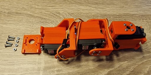
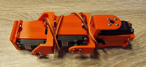
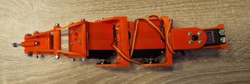
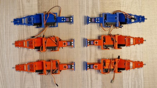
After finishing to print all the 3D parts needed for legs we arrange them in the robot configuration in order to have an idea of assembly order and mounting positions. The result is presented in the next image:
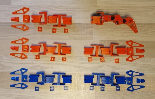
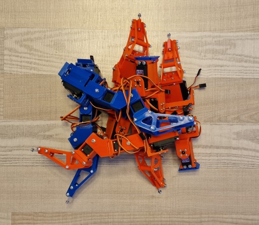
If we include all 18 servo’s in the previous image we get:
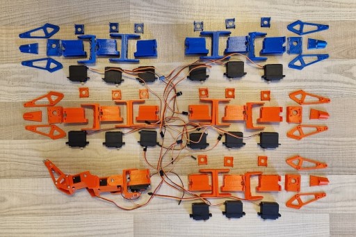
Don’t take into consideration the fully assembled leg that is presented in the image. This one was assembled during the printing process in order to test the tolerances between the parts, and test fit the assembly.
Before starting the assembly process we need to be sure that we have the following screws and nuts:
|
Parts necessary for one Leg |
|||||||
|
Number of parts |
Part Type |
Size |
Length |
Type |
Part #1 |
Part #2 |
Resulting Part |
|
6 |
screw |
M3 |
16 |
countersink |
Servomotor |
Servo_Mount_07 |
Servo Motor Assembly |
|
6 |
screw |
M3 |
20 |
||||
|
12 |
washer |
M3 |
|||||
|
12 |
locking nut |
M3 |
|||||
|
1 |
screw |
M3 |
14 |
Servo Motor Assembly |
Femur_Bracket_04 |
Servo Femur Assembly |
|
|
3 |
washer |
M3 |
|||||
|
1 |
Bearing |
M3 |
685ZZ (5x11x5 mm) |
Servo_Bearing_Fixer_02 |
|||
|
1 |
locking nut |
M3 |
locking |
Servo_Bearing_Center_03 |
|||
|
4 |
screw |
M3 |
10 |
countersink works also |
Servo Femur Assembly |
Femur_Bracket_04 |
Femur Assembly |
|
4 |
nut |
M3 |
|||||
|
1 |
screw |
M3 |
14 |
Femur Assembly |
Servo Motor Assembly |
Femur to Tibia Assembly |
|
|
3 |
washer |
M3 |
|||||
|
1 |
Bearing |
M3 |
685ZZ (5x11x5 mm) |
Servo_Bearing_Fixer_02 |
|||
|
1 |
locking nut |
M3 |
locking |
Servo_Bearing_Center_03 |
|||
|
4 |
screw |
M3 |
10 |
countersink works also |
Femur to Tibia Assembly |
Tibia_Bracket_04 |
Tibia Assembly |
|
4 |
nut |
M3 |
|||||
|
1 |
screw |
M3 |
14 |
Tibia Assembly |
Servo Motor Assembly |
Tibia to Leg Assembly |
|
|
3 |
washer |
M3 |
|||||
|
1 |
Bearing |
M3 |
685ZZ (5x11x5 mm) |
Servo_Bearing_Fixer_02 |
|||
|
1 |
locking nut |
M3 |
locking |
Servo_Bearing_Center_03 |
|||
|
4 |
screw |
M3 |
12 |
countersink works also |
Tibia to Leg Assembly |
Tibia_Base_Plate_05 |
PreLeg Assembly |
|
4 |
nut |
M3 |
|||||
|
2 |
screw |
M3 |
50 |
PreLeg Assembly |
Tibia_Side_1_04 |
Leg Assembly |
|
|
1 |
screw |
M3 |
40 |
Tibia_Side_2_04 |
|||
|
1 |
screw |
M3 |
35 |
Tibia_Foot_Plate_05 |
|||
|
1 |
screw |
M3 |
30 |
Tibia_Spacer_Tube_04 |
|||
|
5 |
nut |
||||||
As you can see, in this table we have the screws, the washer, and the nuts, but at the same time the parts that they connect in.
The full process of assembling one leg is presented next.
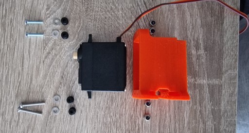
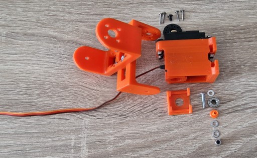
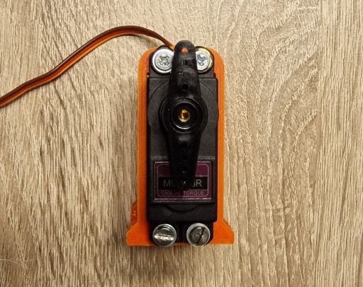
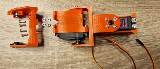
We are starting the assembly process by inserting the servo-motor in its housing which is called: Servo_Mount_07. In order to accomplish this, we need a few screws.
After finishing one, it is better to finish at least 2 more, in order to be able to have the necessary parts for one leg. Or you can do all of them in bulk as we did:
In this next step we will prepare the femur bracket, which is composed of 2 identical parts called: Femur_Bracket_04.
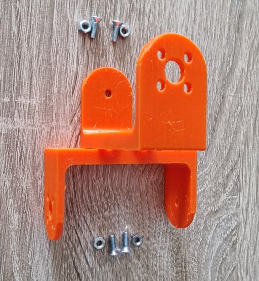
After finishing the previous step, we can take the resulting assembled part and add it to one obtained at step 1 with the help of several nuts and bolts.
As we can see, this step is a little bit more complicated, and we need to detail it a bit more. This means to split it in several sub-steps, as follows:
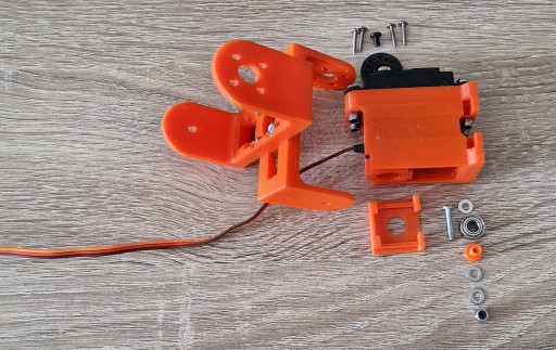
First of all, we need to add the bearing assembly to the femur bracket. The parts need to be mounted in the order presented in the image below:
As we can see, we are introducing two more 3D printed parts, Servo_Bearing_Fixer_02 and Servo_Bearing_Center_03. The part called Servo_Bearing_Center_03 needs to be inserted in the bearing and with the help of the screw and of several washer we need to obtain this:
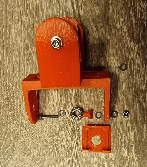
This bearing assembly needs to be mounted on the femur bracket assembly, as follows:
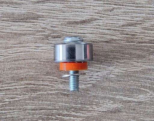
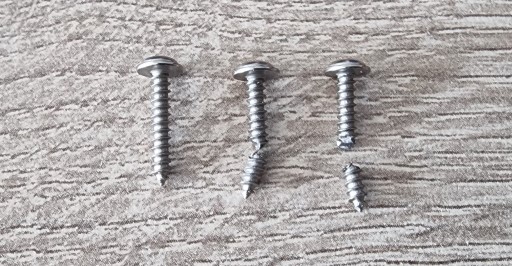
On the other side of the bearing assembly, we need to mount the servo part. This part is from the servo-motor accessories. Before mounting it to the assembly we prefer to pre-thread the plastic with the screws for an easier assembly process.
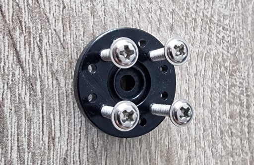
Depending on the length of the plastic screws that came with the servo motor we might need to cut them on some extent. This is needed because if the screws are too long, it will hit the servo when running. Please cut them at an approximative length, as in the image below:
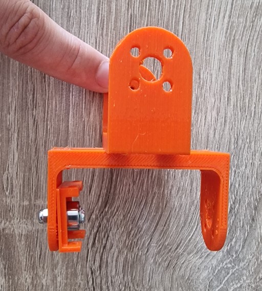
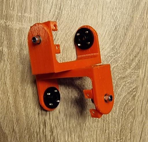
This part needs to be mounted to the femur assembly, like this:
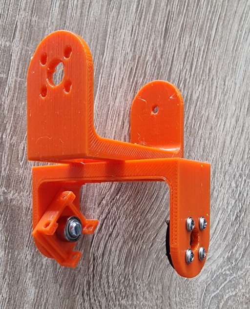
Now, we can repeat these steps on the other side, to be easier to assemble it later. The final result is presented in the next image:
We also need to finish what we have started at the beginning of step 3, and mount everything together:
Before doing this, we need to set the servo-motor at a 90 degrees position. We can accomplish this using another accessory from the servo accessories and move the motor by hand left to right until the middle position looks like this:
Now, all we need to do is to mount the parts together:
If we have prepared our parts as we presented in this tutorial up to this part, this step is fast and easy, and all we need to do is mount the other servo the same way as the first one.
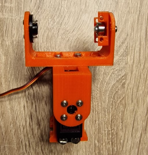
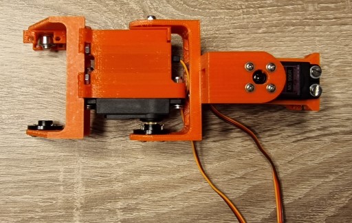
Moving forward, we need to do the bearing assembly also to the Tibia_Bracket_04. After this, we need to mount Tibia_Bracket_04 to the previous resulting assembly, as follows:
Before mounting the Tibia_Bracket_04 part, it will be better to pass the servo wire from the next step, through the hole of the part in order to have an easier assembly process later on. If it is done later, it will require some disassembly because the servo socket doesn’t pass through the hole when the part is mounted.
The final result is presented in the next image:
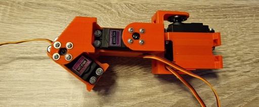
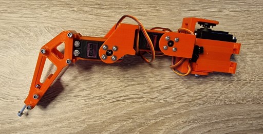
This step is also a little bit more difficult, but this is not due to the parts involved, but due to the position that the servo-motor needs to be set up at. So, the servo-motor needs to be mounted into our assembly like this:
The position that we can see in the above image, is the middle position for the servo-motor. As we can notice, it is difficult to have a mark in order to get our bearings. So, in order to make the process easier, we need to spin the motor, left and right and select a position, that, at the end, we touch the frame as in the next two images:
After we finish all of this, we can go to the next step and add Tibia_Base_Plate_05.
After fixing the screws we obtained the following result:
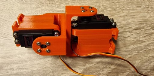
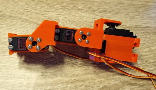
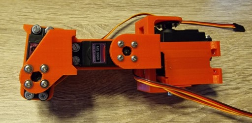
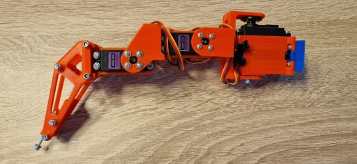
We are getting closer and closer having a complete leg. In this section we will add the following 3D printed parts:
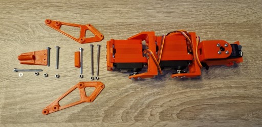
The final result can be observed in the next 2 images:
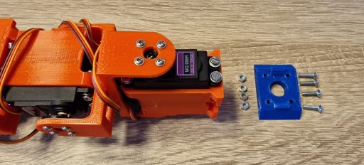
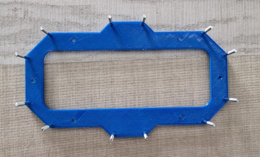
In order to be able to attach a leg to the body we need to mount the 3D printed part Body_Riser_04 to the leg assembly.
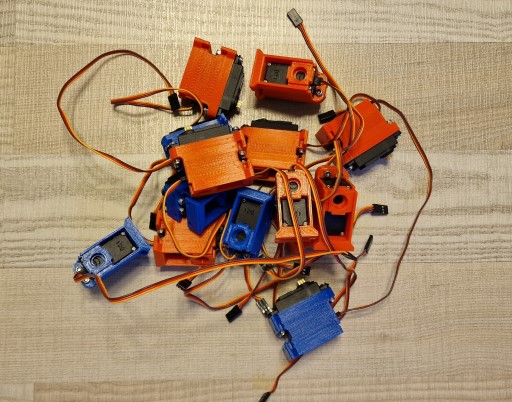
Up to this point we saw how we can assemble one leg for this hexapod. Now, we need to repeat this process five more times. Please be aware that the left legs are different from the right legs. Consult the tables with the 3D printed parts all the time.
Fun times: here’s a pile of hexapod legs!
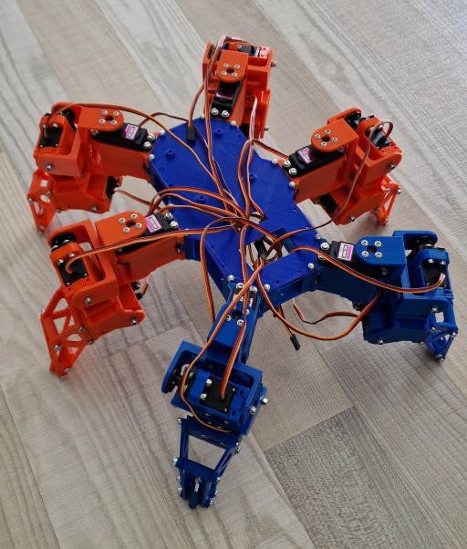
After we have all the legs, the only step that remains is to mount them to the body parts: Body_Bottom_Plate_03 and Body_Top_Plate_04. The process is to add the screws to the Body_Bottom_Plate_03, then add the legs and then add Body_Top_Plate_04 on top.
And here is the mounted hexapod! What do you think of it? Does it look like in the initial drawing? What would you have done differently to improve the process or the robot itself? We look forward to hearing your thoughts and seeing your own hexapods. Stay tuned for part 2, electronics, and for part 3, software.
Alin Jderu has 14+ years of experience in custom robotics for competitions, taking on various roles, such as builder, mentor, referee and judge. He also has 9+ years of experience in IOT and 6+ years of experience in nanotechnology research and development and with organizing scientific education events. He has a programming background in C/C++, Python, HTML, Matlab, LabVIEW, electronics circuit design in Eagle and Proteus, 2D/3D CAD/CAM Design in Catia, Solidworks, Autocad, OpenSCAD and 3D printing, simulation software in Simulink, AmeSim, COMSOL Multiphysics and editing software in Photoshop and Corel Draw. You can also google him ;) He is currently working in IOT R&D at eSolutions.