The second part of the hexapod tutorial series is here! After 3D-printing all the necessary parts and mounting the hexapod in part one of the tutorial, in this second part we approach the electronics. We’ll go through electronics planning, discussing Raspberry Pi, servo motors, end leg switches, sensors, power supply, and battery. Check it out!
As we saw in part one, before going deeper into the tutorial we need to research what options are available out there and choose the best that suit our needs. At the same time we need to take into account the minimum desired functionality for our robot.
In order to set the minimum functionality, first of all we need to establish if we want a smart robot, or just a remote controlled one:
Either way, there will be a need for a controller of such sort, that will have to convert the movement commands such as forward, backward, left and right from either the user or AI to coordinates on X, Y and Z axis and motor commands in order to move the robot.
As we saw in our first part of the tutorial, in our last research, the majority of hexapods out there accomplish this function with either:
or
After seeing all the options that are available, we will go with a raspberry pi board as our main controller for the robot. Even if we decide upon a remote controlled robot, one with AI, or a combination of the two, the board will allow us to have this flexibility.
Before going into details about this tutorial, because we are working with electronics, and we can permanently damage the components if we mess things up, please take special care especially where you find the “Attention:” mark.
As we said before, our electronics will have a raspberry pi as a core, this means that the rest needs to be built around this. Taking this into consideration, we need to add in this equation the following components:
Further on we will go over each one of them and get into details about their specifications and what other components we need to add or to make in order to use them for our hexapod robot.
The brain function for our robot will be accomplished by a raspberry pi board. This device is basically a small, low power and low cost computer. It is capable of doing everything you would expect from a normal computer to do, starting with browsing the internet, playing videos, creating documents, playing games and even program robots, like in this case :D. In order to start a project you only need to add a monitor, a keyboard and a mouse.
Since 2008 when the first raspberry pi was launched, there were several models available for the market. For our robot we will go with the latest version of this board, which is Raspberry Pi 4 Model B, but you can also use the previous one, Raspberry Pi 3 Model B.
As we can see in the following image, this little board is like a real computer:
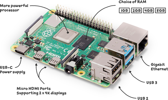
Raspberry pi 4 Model B. Source image: link
The most exciting thing about this board is that it allows us to connect motors and sensors directly to it using the 40 Pin header that is placed on one side as we can see in the next image.
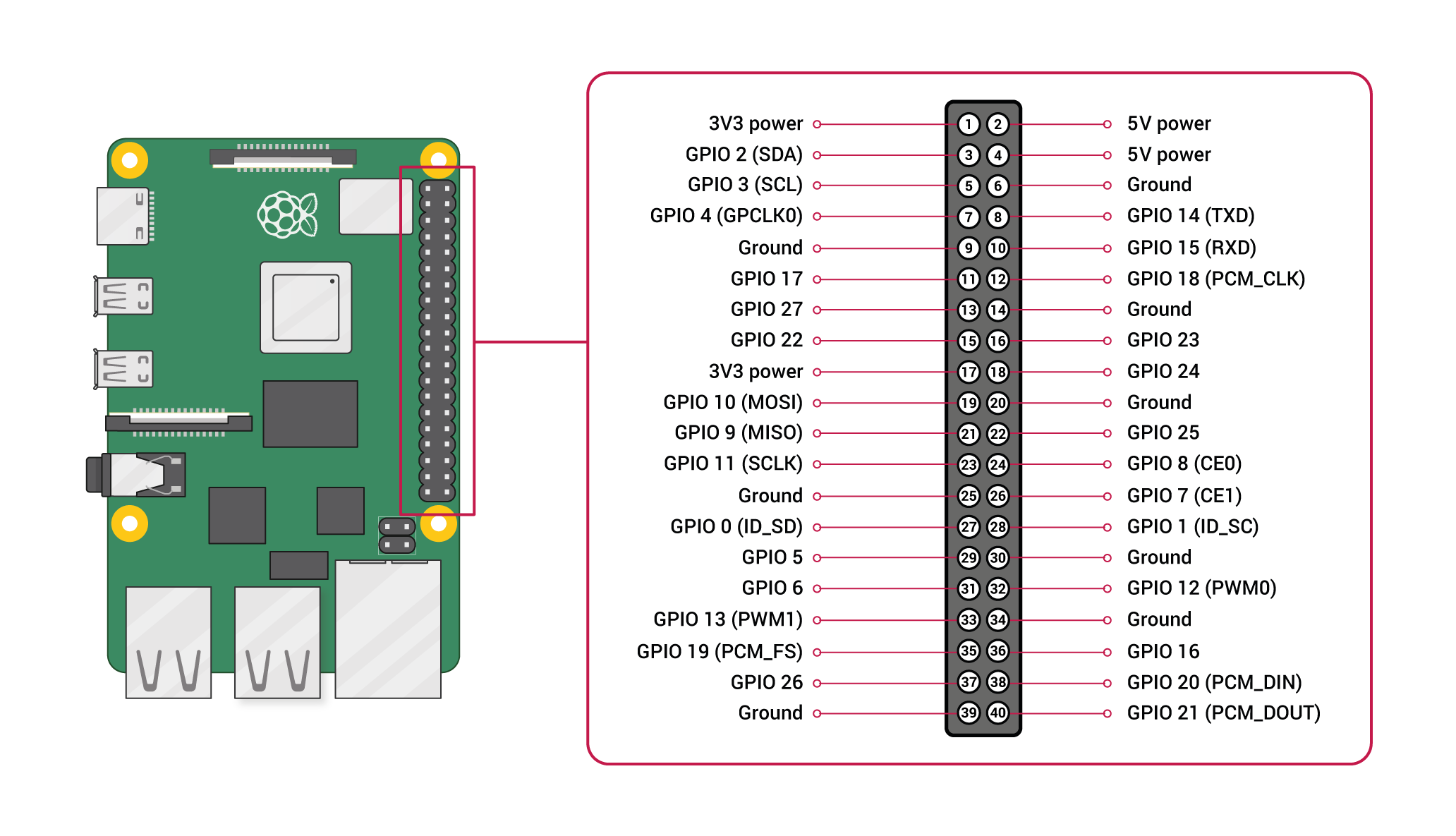
Raspberry pi 4 Model 4 pin header. Source image: link
To be sure that the raspberry pi board has enough general-purpose input/outputs (GPIOs) for our configuration, we need to make a list with our I/O needs, taking into account the fact that our hexapod robot has 6 legs:
That being said, we need a total of 24 of GPIOs from the raspberry pi to only control the robot movement. Since the raspberry pi has 26 GPIOs, we should be covered in this respect.
Another very important aspect we need to take into consideration is the power usage. Since it is a robot that moves around, it can’t be connected to the mains for power, or drag a wire after it. This means that the robot needs a battery, and in order to size it, we need the total power consumption of the robot.
According to the datasheet, a raspberry pi needs a constant voltage of 5V and can eat up to 3A. This means that the board needs a maximum of 15W of power. This information will be used in the power supply chapter.
Due to the fact that we will connect sensors and motors to the raspberry pi board, we will have to take great care of the voltage polarity. Always ground to ground, minus to minus and plus to plus. We will work only with positive voltages so, we will have ground as reference (noted by GND) and plus (noted with VCC or the voltage level used). As for the GPIO’s pins…
The raspberry pi GPIOs are on 3.3v voltage level. All the sensors and devices connected directly to GPIO must have the same voltage level or it will damage the board.
The robot can move around with the help of 6 legs. Those legs are powered by some servo motors. Each leg has 3 of such motors in order to allow the robot to move in all the directions desired by the user or AI.
A servo motor actually is not a dedicated type of motor, it is in fact a term used to describe a closed loop control system. This means that it is using position feedback in order to control its motion and final position.
These motors can be moved to a precise position with a precise speed and acceleration. In fact, our motor is a rotary type actuator, that means we can move it to a precise angular position. In our case, this is accomplished by using a simple DC motor coupled with a potentiometer in order to provide the position feedback.
Regarding the speed and acceleration, because we are using a less expensive version, there is no direct method of control, but we can trick it:
If you want to go deeper into how servo motors work, we found a nice tutorial out there, check it out here.
The servo motors that will be used for our robot as we saw in part one of this tutorial series (the construction part), are some standard servo-motors MG996R.
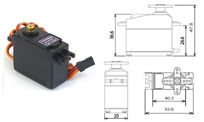
MG996R servo motor. Source image: link
According to its datasheets, in order to control this motor we need to connect 3 wires as follows:
In order to chose the VCC voltage level, we can see in the datasheet that this motor is capable of 9.4 kgf*cm at 4.8V and 11 kgf*cm at 6V (no information regarding 7.2V). Because we need as much power as we can have, it means that we will have to deliver to the motor a voltage of 6V. This translates into the fact that the motor will need 900mA from the power supply in order to deliver the requested power. All of this means that one motor needs a total of 5.4W of power, and for all 6 legs we will need a total of 97.2W of power. We will use this information when we get to the power supply chapter.
In the same datasheet there is one more information related to power consumption, and that is the stall current. This term is used to tell us the consumption when the motor tries to move, but it is stuck (this can happen because it doesn’t have enough torque to move, or some other reason like gearbox damage and so on). Our motors have a stall current of 2.5A at 6V. We will also have to take this information into consideration in the power supply chapter.
Each leg of the robot is fitted with an end switch in order to be able to detect when the robot touches the ground. These switches are some simple standard micro-switches SPDT-type. SPDT-type means that there are 3 electrical connections and usually the middle connection is either connected to one of the other 2 depending if the switch is pressed or not.

Image of the SPDT switch type
Another important aspect of the switch is related to the mounting holes located on the body of the switch. When we designed the robot we used the switches from this link, and this translated in a distance between the holes of 9.5mm.
In order to detect this “button press” or release with the raspberry pi, we need to connect it to one of the GPIOs. Unfortunately we can’t just connect the button, we need to make a little circuit and add a resistor to accomplish this.
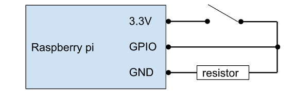
Circuit diagram to connect one button to Raspberry Pi GPIO
Repeat this 6 times and we are done :D. The nice thing about this is that it doesn’t consume almost any power. It will only use some power when the switch is closed (the leg touches the ground), because some energy will pass through that resistor. If the resistor has 10 kOhms, at 3.3V there will be a flow of only 330uA. And if the robot is standing with all the six legs on the ground it will consume a total of 1.98mA.
Here, the possibilities are endless. There are so many types of sensors that we can add and use for such a robot, the only limitation is the remaining free GPIOs. And even this is not actually a limitation because we can add another controller to expand the number of GPIOs or even add a GPIO expander :D. Even if the sensor has a different logic voltage level, it can’t stop us from using our desired sensor.
That being said we will go through some of the main sensor categories and then describe in more detail the one that we will use for this robot. And the main sensor categories are:
In order to cover our main concern, that we will remain out of GPIOs, let’s learn more about the device that solves this problem.
A GPIO expander is also called a Multiplexer. This type of device uses a small number of GPIOs to control a bigger number of them. For example the CD74HC4067 from the image below needs only 5 GPIOs to control 16 GPIOs. It has 4 pins used for controlling (S0, S1, S2, S3) a GPIO that carries the signal (IN or OUT on SIG connection) to up to 16 GPIOs (C0 to C15). The only downside is that you can only use one of the C0 to C15 at a time, but we will bypass this by reading each of them very very fast :D.
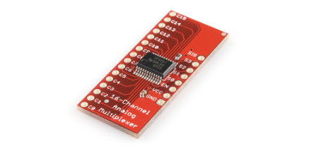
CD74HC4067 multiplexer. Source image: link
We can even parallelize this to go up to 32 GPIOs with only 5 pins for controlling. We can put in parallel the S0 to S3 pins of two such as CD74HC4067 multiplexers and have only SIG GPIOs separated.
If we look carefully at the datasheet, we can see that the model with “HC” can work with voltages between 2V to 6V (which is ideal for our case because it covers the 3.3V voltage needed for the raspberry pi GPIO), the model with “HCT” can work with voltages between 4.5V to 5.5V.
This type of electronic module allows us to control devices or use sensors that have a different logic voltage level. For example, let’s say we want to use a sensor that measures the distance between the robot and the object. This sensor reports the distance on a pin with a voltage level of 5V and our controller accepts a maximum of 3.3V. We can’t connect them directly, this will for sure damage the controller board, but we can add a logic level converter between them and, like this, everything will be safe.
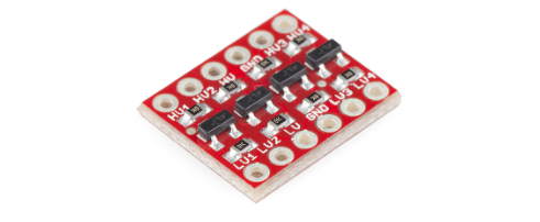
4 channel bidirectional logic level converter. Source image: link
Due to the fact that this device is a mobile device and it will use a battery, it is very important to know the charge state of it. We will accomplish this either by:
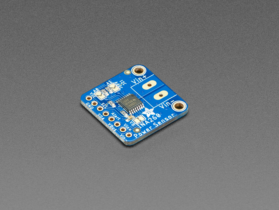
Source image: link
or
With all of these being said, we can use the formula Vout = (Vs * R2) / (R1 + R2) where Vs is the battery voltage, R1 and R2 are the 2 resistors needed for this to work, and Vout is the voltage output that goes to the raspberry pi GPIO.
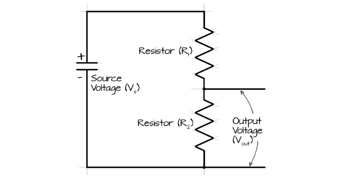
Image and formula source: link
In our case, if we choose an R1 of 100 kOhm resistance and R2 of 33 kOhms resistance and the battery is fully charged (max voltage of 12.6V), the output voltage Vout will have a value of 3.126 which is below the maximum 3.3V limit. This will also allow us to have a margin for error.
At the same time, please be aware of the tolerance of the resistors and choose the smallest one (0.1% should be fine), because this will directly influence the accuracy of the voltage measurement.
This circuit will have a total resistance of 133 kOhms and at 12.6V will use a total of 0.09mA.
After all of this, we added all the information in a table in order to see the maximum power that is needed from the battery in order to bring the robot to life.
|
Component |
Power consumption [W] |
Number of components |
Total Power Consumption |
|
Raspberry pi |
15 |
1 |
15 |
|
Servo Motors |
5.4 |
18 |
97.2 |
|
End leg switches |
0.001089 |
6 |
0.006534 |
|
Voltage sensor |
0.00119 |
1 |
0.00119 |
|
Total power needed |
112.207724 |
||
As we can see in the table above, we need a total of 112W of power for the robot. To choose a proper battery for this we need to increase this power by 20%. The reason for this is that if, for example, a battery has a maximum capacity of 112Wh we can’t actually get the full power out of it without damaging the battery in the process. And because of this we actually need about 135W of power.
The next step is to decide how much time we want the robot to be able to move between battery charges. For example, If we need one hour of autonomy we will need a 135Wh battery, and half of this for only 30 min of autonomy. For our use case, 30 min will be plenty of time.
The battery used for this robot will be LiPo battery type. We will use this type of battery because it is lite and it can provide high discharge rates. This rate gives us how fast we can drain the battery without damaging it and it is noted with a number followed by the letter C. LiPo batteries can go with the discharge rate as high as up to 140C. This means that a battery with a capacity of 1000mAh for example, can provide up to 140 Amps if needed.
Now that we have decided on our battery type we need to select the voltage level for it. To accomplish this, we need to take into account the voltage levels used by our components, and those are 5V and 6V. The most power-hungry components are the motors with the 6V voltage level. We need to find a battery as close as possible to this voltage level in order to minimize the losses during voltage regulation. We can use a battery with:
Knowing this, we will have to use a battery with a 11.1V and 6000 - 8000 mAh capacity.
As we saw earlier, we need to use a battery of 11.1V in order to have a decent autonomy for our robot. But, this voltage level is not even close to the highest one that we need (the 6V one).
In order to reduce the battery voltage level to satisfy our robot requirements we can use some voltage regulators for each of the voltage levels that we need.
We can accomplish this by using a linear voltage regulator. One example of such a device for a 6V voltage level is 7806 (7805, the 5V version of this regulator was first introduced in 1972 and it is still in use).
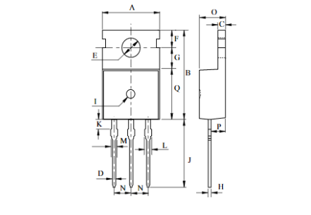
Image from this datasheet
Unfortunately, using this type of regulator will generate a lot of losses in the form of heat (about 4.6W for our case) and can deliver a maximum of 1A. The efficiency of this regulator can be as bad as 50%. But it is not all lost, since now there are more advanced solutions out there, like switching power supplies, and we can find an example here.
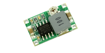
Source image: link
This one is able to deliver a continuous 1.8A and a peak of 3A, which means that it can drive up to 2 servo motors (2 * 0.9A) and still have some room for error. Its efficiency is 96%.
That being said, we will use the later solution for the voltage level (6V) needed for the servo motors. In order to cover the 5V level for the raspberry pi we need a power supply that outputs a 1.8A continuous with a maximum of 3A which is exactly as the above switching power supply ratings. This should be enough because we don’t plan to add peripherals to the raspberry pi.
To charge the battery please use dedicated solutions, because the LiPo batteries need to be handled with care during the charging process. Such a solution can be a charger like the one from this link.
And we’re done for now! Now that we have made our plan, see you in the next part where we will build and assemble all these elements into our hexapod robot.

Alin Jderu has 14+ years of experience in custom robotics for competitions, taking on various roles, such as builder, mentor, referee and judge. He also has 9+ years of experience in IOT and 6+ years of experience in nanotechnology research and development and with organizing scientific education events. He has a programming background in C/C++, Python, HTML, Matlab, LabVIEW, electronics circuit design in Eagle and Proteus, 2D/3D CAD/CAM Design in Catia, Solidworks, Autocad, OpenSCAD and 3D printing, simulation software in Simulink, AmeSim, COMSOL Multiphysics and editing software in Photoshop and Corel Draw. You can also google him ;) He is currently working in IOT R&D at eSolutions.